Arduino Lenticular Clock

Learn how to build a secure and efficient Lenticular Clock with Arduino!

Arduino RFID Project

About the Project

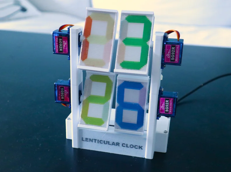
After making my Moire Clock a got interested in a very similar effect: lenticular animations. You probably have seen this effect before, e.g. on post cards. I remember having a ruler in primary school with a picture of dinosaurs on it that changed depending on the viewing angle.

Supplies

  • 4pcs SG92R 270deg servo motors actually you only need 2 pcs of 270deg servos, the other 2 pcs can be 180deg
  • PCA9685 PWM driver board
  • Wemos D1 mini ESP8266

Step-by-Step Guide

Step 1

Choosing the Right LPI.

Step 2

Creating the Lenticular Print

Step 3

Attaching the Print to the Lenticular Sheet

Because of manufacturing tolerances of the lenticular sheet and also tolerances of your printer you need to determine the exact LPI value that you will use for interlacing. There are several softwares that can generate calibration sheets. I tried out the software from 3Dependable and fPitch. For some reason though the calibration did not work very well and I ended up generating the final print with different LPI values and then chose the one which gave the best results when placed below my lenticular sheet.

There are several softwares that can be used for interlacing the images, I used grape which is freeware. At first, I created pictures of each individual digit from 0 to 9 all with the same size of 52.5x30mm. I used a different color for each digit which helps to distinguish them more clearly and also has the advantage of being able to participate in the "colors of the rainbow" contest on instructables ;-)

Project Code

                /*
                State change detection (edge detection)
              
                Often, you don't need to know the state of a digital input all the time, but
                you just need to know when the input changes from one state to another.
                For example, you want to know when a button goes from OFF to ON. This is called
                state change detection, or edge detection.
              
                This example shows how to detect when a button or button changes from off to on
                and on to off.
              
                The circuit:
                - pushbutton attached to pin 2 from +5V
                - 10 kilohm resistor attached to pin 2 from ground
                - LED attached from pin 13 to ground through 220 ohm resistor (or use the
                  built-in LED on most Arduino boards)
              
                created  27 Sep 2005
                modified 30 Aug 2011
                by Tom Igoe
              
                This example code is in the public domain.
              
                https://www.arduino.cc/en/Tutorial/BuiltInExamples/StateChangeDetection
              */
              
              // this constant won't change:
              const int buttonPin = 2;  // the pin that the pushbutton is attached to
              const int ledPin = 13;    // the pin that the LED is attached to
              
              // Variables will change:
              int buttonPushCounter = 0;  // counter for the number of button presses
              int buttonState = 0;        // current state of the button
              int lastButtonState = 0;    // previous state of the button
              
              void setup() {
                // initialize the button pin as a input:
                pinMode(buttonPin, INPUT);
                // initialize the LED as an output:
                pinMode(ledPin, OUTPUT);
                // initialize serial communication:
                Serial.begin(9600);
              }
              
              
              void loop() {
                // read the pushbutton input pin:
                buttonState = digitalRead(buttonPin);
              
                // compare the buttonState to its previous state
                if (buttonState != lastButtonState) {
                  // if the state has changed, increment the counter
                  if (buttonState == HIGH) {
                    // if the current state is HIGH then the button went from off to on:
                    buttonPushCounter++;
                    Serial.println("on");
                    Serial.print("number of button pushes: ");
                    Serial.println(buttonPushCounter);
                  } else {
                    // if the current state is LOW then the button went from on to off:
                    Serial.println("off");
                  }
                  // Delay a little bit to avoid bouncing
                  delay(50);
                }
                // save the current state as the last state, for next time through the loop
                lastButtonState = buttonState;
              
              
                // turns on the LED every four button pushes by checking the modulo of the
                // button push counter. the modulo function gives you the remainder of the
                // division of two numbers:
                if (buttonPushCounter % 4 == 0) {
                  digitalWrite(ledPin, HIGH);
                } else {
                  digitalWrite(ledPin, LOW);
                }
              }